The most used element in radiotechnical devices is a resistor (the old name is resistance). The main characteristic of a resistor is resistance, measured in ohms. Two types of resistors are produced: stable and general purpose. Production of stable resistors is expensive, so they are used in expensive high-precision equipment. We will use general-purpose resistors. Their resistance can vary by up to 10% (depending on the TCS). Normal resistors have a positive TCR (Temperature Coefficient of Resistance), which means that the resistance increases with increasing temperature. Only one simple element is negative: carbon.
One of the main characteristics is the power dissipation. The power dissipation is the power that a resistor can dissipate without being damaged. It is measured in watts. It is calculated by the formula power=current2 * resistance, or P = I2R
Every substance has its own resistance, some are very large (wood, plastic), others are small (metals, liquids). The resistance depends on the material (gold has less resistance than aluminum), on the length of the conductor (direct correlation: the longer the greater the resistance) and on the area of the cut of the conductor (the greater the area, the less resistance).
Now let’s talk about the use of permanent resistors in circuits.
If you did not find a resistor with the right resistance when assembling the circuit, you can put two or more resistors in series (their total resistance will be the right resistance). You can put them in parallel and find their resistance by the formula 1/Robsh = 1/R1 + 1/R2 + 1/R3.
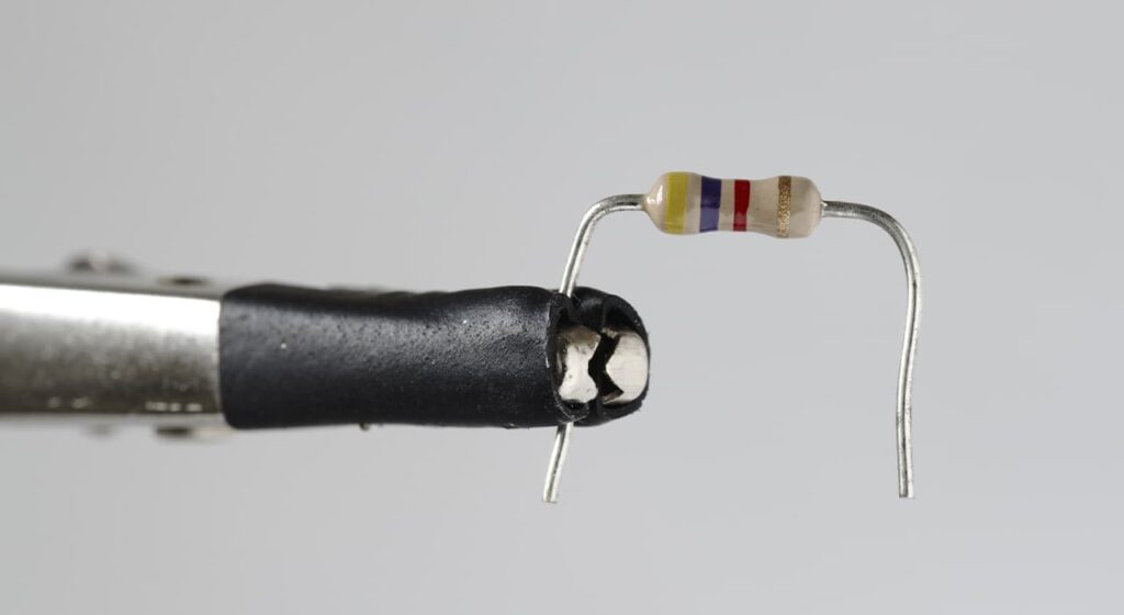
Basically we will use carbon resistors. If you break it down (for the sake of interest, of course), you will see a layer of ceramic covered with a thin carbon film.
Most resistors are labeled with color bars (usually four, less often five), or a numerical designation. For example, 1R means that the resistor has a resistance of 1 ohm, 1.5K means 1.5 kilohms (1500 ohms). You can find the resistance by color banding using an online service: resistor color-coding calculator.
There are also variable resistors that have the ability to change their resistance. They are used to change current, voltage, etc. (for example: change the volume and tone). Most often on a circuit diagram are shown as follows:
Variable resistor designation
About their types below.
Variable resistors are:
1) Single and twin
2) Single and multi-turn
3) With or without switch
By nature of resistance change:
1) Linear i.e. In proportion to the angle of rotation of the axis (group A)
2) Inversely logarithmic, i.e. gradually increasing at first, and then sharply increasing (group B)
3) Logarithmic (group C)
4) And others (groups E, I).
There are wire-wound and non-wire-wound (film) variable resistors. Wire-wound resistors are characterized by high stability, a relatively low level of their noise and low TCR.